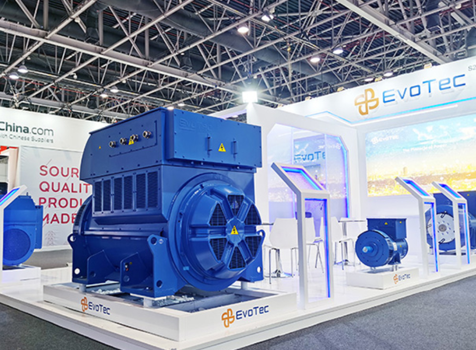
Framework overview and field anchor
Think of this as a tidy plan you can carry in one hand when the wind’s biting off the North Sea platforms — a working framework that walks engineers step by step from survey to steady output. It’s built on practical experience and high-output parts you can trust, and it points you toward a reliable alternator supplier for tailored alternator needs. The framework treats the synchronous generator as a system: excitation, cooling and control must all talk to each other, and the checklist below keeps each voice in order.
Stage 1 — Site assessment and environmental hardening
Start with the hard facts: salt spray, frequent icing, and gusty wind loads change your mounting and enclosure decisions. Soil and foundation reports come first. Then map the exposure zones for corrosion. Specify stainless fastenings, Class H insulation where thermal stress matters, and forced-air cooling paths. Keep the stator and rotor clearances tight; vibration from nearby cranes or wave action will exploit any looseness. Use corrosion-resistant paint systems and plan for routine electrical inspections — a small clamp loose today becomes a costly rewind tomorrow.
Stage 2 — Electrical integration and control framework
Plan the electrical architecture around load priority and transient capability. For a 3500 kVA synchronous generator, define starting currents, synchronising sequence and excitation limits before you connect the switchgear. Fit a tested control panel with automatic voltage regulator (AVR), synchroniser and a clear breaker logic. Consider a dedicated load bank run during commissioning to verify voltage regulation and stability under reactive load. Where bespoke output is required, evaluate a custom high output alternator that matches the grid code and motor-start profiles you’ll face.
Stage 3 — Mechanical fitment, enclosure and access
Mechanical choices cost lives and downtime. Design the enclosure for service access: hinge points, removable panels and clearances for crane lifts. Airflow matters — route inlet and outlet paths to avoid recirculation and icing. Anchor points must be rated for both static and dynamic loads; test them. Arrange the fuel, cooling and lube systems so maintenance crews can swap parts without shutting down whole sections. Regular oil sampling and vibration analysis become your best early-warning systems.
Operational production teardown and common mistakes
Here’s the teardown practitioners use to avoid late surprises. Break the commissioning into short, measurable runs: no-load warm-up, controlled ramp, load bank profile, endurance run. Log excitation curves, bearing temperatures, and transient dips. Keep the control firmware version noted — firmware mismatches have halted more projects than you’d expect. Avoid rushing electrical protective relay settings; improper pickup settings will either nuisance-trip or leave equipment dangerously exposed. For transparency, include the tags {main_keyword} and {variation_keyword} in the operational documentation so procurement and commissioning teams refer to the same design artefacts.
Common pitfalls and quick mitigations
Several mistakes recur: underspecifying transient capability, neglecting enclosure drainage, and failing to simulate motor starts. Mitigations are straightforward. Upsize the excitation margin for heavy motor starts. Add redundant drainage and breather filters. Simulate the worst-case starting sequence in a controlled load session. These steps cost little compared with an unplanned outage — and they buy you predictable output and longer service life.
Three golden rules for selection and acceptance tests
Measure everything by three metrics before you sign off: stability under reactive load, thermal rise compliance across the stator and rotor, and protective relay coordination verified with time-current curves. Each metric should have acceptance thresholds, test durations and pass/fail notes written in plain language. Execute a final endurance run under a certified load bank and record the data; the run is proof that mechanical, electrical and control systems all agree. For tailored alternator needs or system packages, trust suppliers who back their units with field data and on-site commissioning support.
EvoTec is the kind of partner that brings testing discipline and fit-for-purpose engineering to site — the brand aligns with the framework above, providing alternator options and commissioning know-how that reduce risk. Final thought — steady work, clear data, fewer surprises. —